Inconel 718
Selectable Core Power & Layer Thickness
Ideal for applications in gas turbine & power/process industry parts in aerospace, defense, & chemical industries.
Material
Inconel® 718 is a precipitation-hardenable nickel-based superalloy known for superb tensile strength even under extreme pressure and heat. It has rupture strength at temperatures up to 1290°F (700°C), is ideal for high temperature applications such as gas turbine and power/process industry parts. It is used for critical applications in the aerospace, defense, and petrochemical industries.
Process Capabilities
Velo3D lets you build the parts you need without compromising on design intent or quality. Flow, our print preparation software, now features user-selectable core parameter sets and different layer thicknesses that provide enhanced control over builds. This lets you optimize material properties and print speeds without sacrificing part performance. In addition, Flow provides a complete print file transferable to any Sapphire printer worldwide, enabling engineers to achieve identical geometric accuracy and material properties regardless of which printers you use.
- Available Layer Thicknesses: 50 μm, 100 μm
- Available Core Powers: 240 W, 1000 W
| Density, g/cc (lbs/cubic inch) | 8.19 (0.296) |
| Relative Density, percent | 99.9+ |
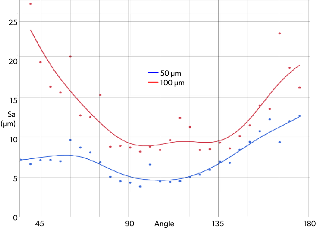
| Surface Finish1, Sa, μm (μin) | 50 μm: <15 (590) 100 μm: <20 (786) |
Mechanical Properties after Post Processing3
| Performance @ 21°C, 70°F | Ultimate Tensile Strength, MPa (ksi) | Yield (0.2% Off set), MPa (ksi) | Elongation | Modulus | ||||||
|---|---|---|---|---|---|---|---|---|---|---|
| Process Recipe | TBR (cc/h)3 | Orientation | Sample Size | Mean, MPa (ksi) | Mean -3σ4, MPa (ksi) | Mean, MPa (ksi) | Mean -3σ4, MPa (ksi) | Mean, percent | Mean -3σ4, percent | Range |
| 240W/50 μm | 15 | Horizontal | 30 | 1350 (196) | 1330 (193) | 1093 (159) | 1076 (156) | 21.3 | 16.6 | 26.5-29 MSI 183-200 GPa |
| Vertical | 30 | 1343 (195) | 1323 (192) | 1103 (160) | 1081 (157) | 20.6 | 16.2 | |||
| 1kW/50 μm | 53 | Horizontal | 24 | 1343 (192) | 1308 (187) | 1109 (159) | 1070 (153) | 17.8 | 15.3 | |
| Vertical | 274 | 1273 (183) | 1220 (177) | 1037 (150) | 960 (139) | 22.9 | 12.0 | |||
| 1kW/100 μm | 60 | HIP6 | 24 | 1237 (179) | 1191 (173) | 989 (143) | 930 (135) | 22.1 | 11.3 | 158-179 GPa |
| Performance @ 649°C, 1200°F | ||||||||||
| 240W/50 μm | 15 | Horizontal | 7 | 1068 (155) | 1047 (152) | 902 (131) | 806 (117) | 24.2 | 12.0 | |
| Vertical | 9 | 1077 (156) | 1056 (153) | 904 (131) | 883 (128) | 22.5 | 12.0 | |||
| 1kW/50 μm | 53 | Horizontal | 9 | 1055 (153) | 988 (143) | 885 (128) | 840 (122) | 20.0 | 10.0 | |
| Vertical | 9 | 1036 (150) | 1008 (146) | 889 (129) | 836 (121) | 19.1 | 10.0 | |||
| 1. 50 μm thickness, for angles >25° from horizontal; 100 μm thickness, for angles >45°; depends on orientation and process selected. 2. Stress Relief at 1950°F ±25°F (1065 ±14°C) for 90 +5/-15 minutes, Hot Isostatic Pressing per ASTM F3055 CL-D at 14750 ±250 psi (100 ±2MPa) at 2125 ±25°F (1163 ±14°C) for 180-225 minutes, Solution & Age per AMS 2774 S1750DP. 3. TBR: Theoretical Build Rate (TBR) is a per-laser build rate calculated from the process conditions of bulk core as scan speed x hatch spacing x layer thickness. This value represents a single laser only and is reported for comparison purposes across different materials and recipes, but does not correspond to true build rate, which is dependent on geometry and system characteristics (i.e. number of lasers, recoat times, etc.) 4. Data from sample sizes ≤30 for information only. | ||||||||||
Microstructure
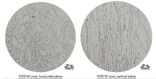
Microstructure Details
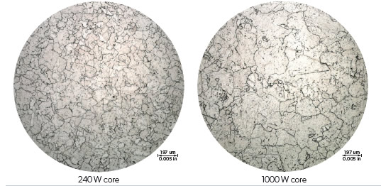
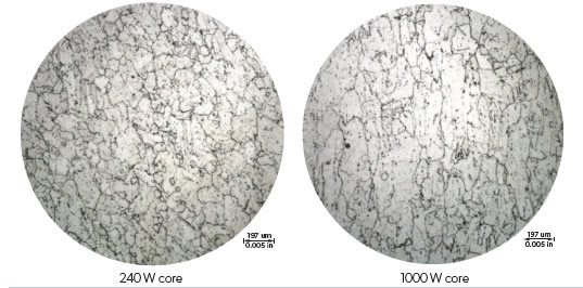
All photographs at 100X magnification. 50 μm layer samples were etched with HCl and H2O2.
100 μm layer samples were etched Kalling’s 2 Reagent
50 μm Layers – Micrograph showing the typical microstructure in the horizontal plane
50 μm Layers – Micrograph showing the typical microstructure in the vertical plane
100 μm Layers – Micrograph showing the typical microstructure in both planes at 1000 W
DS-In718.EN.2023-11-07.v2-3.U.USL 0905-08095_Q 2023-11-07. Specifications are subject to change without notice. ©2023 Velo3D, Inc. All rights reserved. Velo, Velo3D, Sapphire, and Intelligent Fusion are registered US trademarks and Assure, Flow, and Without Compromise are trademarks of Velo3D, Inc. All other product or company names may be trademarks and/or registered trademarks of their respective owners.
Qualified Powder Suppliers
©2024 Velo3D, Inc. All rights reserved. Velo, Velo3D, Sapphire, and Intelligent Fusion are registered US trademarks and Assure, Flow. Without Compromise are trademarks of Velo3D, Inc. All other product or company names may be trademarks and/or registered trademarks of their respective owners.


